





Galería subterránea integral de tubería de componentes prefabricados, proceso de producción detallado.
En primer lugar, la configuración del lugar.
Sitio prefabricado
1. El sitio se selecciona de acuerdo con la situación real del proyecto. El sitio adopta una administración cerrada para configurar la importación y exportación, y el camino de acceso a la construcción está reservado en el área de planificación del sitio, y se cuelgan varios letreros en la importación y exportación de acuerdo con las regulaciones.
2. El diseño del sitio de prefabricación debe estar en estricta conformidad con los requisitos de la fábrica estándar, cumplir con los requisitos del sistema de gestión de seguridad y salud ocupacional y medio ambiente y las instrucciones de operación de HSE, y establecer varias instalaciones de protección del entorno de seguridad. Debe estar completamente equipado para cumplir con los requisitos de producción segura y civilizada, descarga de aguas residuales y eliminación de basura. Estrictamente de acuerdo con las disposiciones pertinentes de los departamentos del gobierno local.
3. Limpie el sitio prefabricado, nivelando, vibrando y compactando, colocando una base de macadán estabilizada con cemento de 20 cm de espesor, alisando y vibrando y compactando. La carretera principal de la planta vertirá concreto comercial C20 de 15 cm de espesor sobre la base de macadán estabilizada con cemento. , área de instalación, prefabricación, área de producción, galería de tuberías integradas área de colocación de conservación natural que vierte concreto comercial de 10cmC20. En la posición de montaje del riel de la grúa pórtico, la profundidad de la excavación es de 60 cm, y el hormigón se vierte y se coloca la vía. También haz estas tres cosas:
(1) El sitio debe limpiarse y nivelarse, incluidos los sitios prefabricados, los cinturones de trabajo de construcción y las vías de transporte existentes, y los pasajes en sitios prefabricados.
(2) En el sitio prefabricado, se deben limpiar las piedras, las malezas, los árboles, las estructuras, etc. que afectan el paso o las obras de construcción de la maquinaria de construcción, se deben nivelar la zanja y la cresta, y las áreas bajas con el agua acumulada se debe drenar y llenar, si es necesario, cambiar. Rellene, garantice completamente la planitud del terreno y la capacidad de carga y compresión.
(3) La limpieza y la nivelación del sitio de prefabricación se llevarán a cabo para salvar la adquisición de tierras o la ocupación de la tierra, no obstruir el tránsito, no dañar los edificios, instalaciones, monumentos, etc., para evitar la contaminación ambiental y la erosión del suelo.
4. Prefabricación del área de instalación y procesamiento de barras de acero, área de producción de vaporización de prefabricación de galería de tubería integrada, galpón de conservación natural de galería de tubería integrada, área de almacenamiento de galería de tubería integrada y otras áreas funcionales. El área de la oficina y la sala de estar se establecen de acuerdo con la situación real, y la entrada y salida prefabricadas del campo se configuran como una sala de guardia. En segundo lugar, el proceso de producción.
Diagrama de flujo del proceso de producción
1. Materiales de construcción de ingeniería de refuerzo que ingresan al sitio, inspección de muestreo, procesamiento de acero, unión de barras de acero, instalación.
(1) Inspección de aproximación de refuerzo a. Rebar es acero laminado en caliente de grado HPB300 y barra de acero de grado HRB400 laminado en caliente. La resistencia estándar de la barra de acero cumple con los requisitos de 4.2.2 de GB50010-2010. La barra de acero acanalada cumple con el acero para hormigón armado: Parte II: barras de acero acanaladas laminadas en caliente (GB1499.2-2007); Las barras de acero redondas y ligeras cumplen con los requisitos del acero para hormigón armado: Parte I: barras de acero acanaladas laminadas en caliente (GB1499.1-2008). La placa de acero está hecha de acero Q235-B, el electrodo de soldadura de acero de grado HPB300 está soldado con electrodo de tipo E43, y el acero de grado HRB400 está soldado con electrodo de tipo E55. segundo. Antes de que el acero ingrese al sitio, verifique la variedad, el grado, la especificación, la cantidad y la lista de materiales en estricta conformidad con los requisitos, si el certificado de calidad del producto, el informe de inspección de fábrica y el informe de reinspección son completos y válidos. La prueba de propiedades mecánicas debe estar de acuerdo con los estándares relevantes. do. Antes de que el acero ingrese al campo y antes de usarlo, verifique la calidad de la apariencia de la barra de acero, ya sea recta, sin daños, sin escoria incluida en la superficie, piel gruesa, grieta, manchas de aceite, óxido granular o escamoso, color uniforme , ver el diámetro de la barra de acero Cumplir con los requisitos, para no afectar la resistencia del acero y el rendimiento de anclaje. Las placas de acero, las varillas de soldadura, etc. se inspeccionan con los elementos de inspección de las barras de acero antes de ingresar al sitio.
(2) Almacenamiento de barras de acero a. Las barras de acero que ingresan al sitio se almacenan en el área de almacenamiento de la barra de acero de acuerdo con la variedad, especificación y grado. Los materiales son almacenados por el personal de materiales y los custodios. La barra de acero debe cubrirse con una almohadilla para evitar la oxidación. segundo. Compruebe si la barra de acero tiene el certificado de fábrica y el informe de inspección de fábrica y el informe de reinspección. Compruebe la calidad de la apariencia y el diámetro del volumen representativo. La barra de acero debe inspeccionarse exhaustivamente por su índice de calidad. Según la inspección de lotes, el diámetro y la desviación de peso son los mismos que en la misma fábrica, el mismo número de horno, la misma especificación, el mismo proceso de producción y la barra de acero de 60 toneladas que ingresa en el mismo sitio de construcción al mismo tiempo es Un lote de inspección, menos de 60 toneladas. También como lote de prueba, realizar muestreos testigos. El muestreo de las barras de acero será realizado por el ingeniero supervisor. Se tomarán dos barras de acero para tomar dos piezas de prueba de tracción, cada una con una longitud de aproximadamente 450 mm, y dos piezas de prueba dobladas en frío con una longitud de aproximadamente 350 mm, colocadas en la caja de prueba, y luego supervisadas para sellar o monitorear la sala de prueba Si el resultado del informe de reexamen no está calificado, se tomará una doble muestra y se volverá a analizar. Los resultados del informe de reexaminación deben ser calificados, y el ingeniero de supervisión profesional debe firmar la aprobación, y el lote de barras de acero puede usarse en el procesamiento. El almacenamiento y almacenamiento de otros materiales se llevará a cabo mediante aislamiento de humedad.
(3) Procesamiento de barras de refuerzo Antes del procesamiento, de acuerdo con las especificaciones de diseño y la longitud y la cantidad, combinadas con diferentes técnicas de procesamiento, la longitud de cada barra de refuerzo se determina mediante el cálculo para garantizar la precisión. Durante el procesamiento, verifique si hay algún error u omisión en la tabla de borrado. Compruebe la tabla de materiales para cada tipo de barra de acero. Después de estas dos inspecciones, presione la tabla de materiales para liberar la muestra real. Una vez que se califica la producción de prueba, se puede procesar en lotes. Las barras de acero buenas deben apilarse ordenadamente. La superficie de la barra de acero debe estar limpia y la grasa, la suciedad y el óxido deben limpiarse antes de su uso. Las barras de acero se enderezan y se enderezan mecánicamente. Las barras de acero después del alisado no deberán tener curvatura local, curvas muertas u pequeñas olas. El corte de la barra de acero debe basarse en el número, diámetro, longitud y cantidad de la barra de acero. La longitud y la longitud de la barra de acero deben romperse y el material corto debe romperse primero, y la cabeza corta de acero debe reducirse y acortarse tanto como sea posible para ahorrar acero y reducir las pérdidas. Cuando la barra de acero se dobla, el replanteo determina el punto de flexión y el ángulo de flexión en función de la resistencia de rebote de cada barra de acero. Antes de la flexión formal, las barras de acero que se han doblado en grandes cantidades se someterán a una flexión de prueba y los datos técnicos pertinentes se determinarán antes de la flexión por lotes. Después de doblar la barra de acero, el arco forma un arco. Después de la flexión, el tamaño no es mayor que el tamaño de cegamiento. El valor de ajuste de flexión debe ser considerado. El diámetro de flexión D de la barra de acero doblada y la curva de la parte media no es inferior a 5 veces el diámetro de la barra de acero. La longitud de la barra de acero debe considerarse globalmente de acuerdo con el tamaño del componente, el grosor de la capa protectora y el valor de ajuste de la flexión de la barra de acero. La desviación permitida del procesamiento de la barra de acero no debe exceder la especificación. Para barras de acero con material de acabado insuficiente, el método de soldadura por presión de la junta a tope se utiliza para topear la longitud del pie y luego doblar. El soldador a tope debe ser entrenado en un proceso especial de soldadura a tope y ser muestreado para su inspección. Después de que se forman las diferentes barras de acero, la desviación permitida no debe exceder la especificación: la longitud total de los nervios de fuerza debe ser de ± 10 mm; la desviación de la longitud de cada parte de los estribos será de ± 5 mm; la desviación de las costillas dobladas será de ± 20 mm del miembro, gran volumen El concreto es de ± 30 mm; la desviación de la esquina de acero es de 3 mm; la costilla redonda de 6 ~ 12 mm se coloca en el estribo y la longitud del gancho final es de 75 ~ 105 mm según el diámetro de la costilla principal. El cálculo específico antes de determinar la supresión, las barras de acero procesadas se clasifican y almacenan, y se evita que las barras de acero formadas se deformen durante el almacenamiento y el transporte.
Esqueleto trenzado (acero reforzado) encofrado de acero.
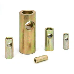
Dificultades: la dificultad para hacer las costillas principales del tubo superior rectangular es la costilla exterior de la costilla exterior. Cada anillo consta de cuatro barras de acero con dos arcos, cada uno de los cuales forma un anillo de refuerzo de tubo superior rectangular. El radio del arco es demasiado pequeño, el segmento del arco curvo es corto y la precisión es alta. . Solución: antes de doblar las barras de acero, márquelas en la intersección de cada arco. Luego, el arco de grado de R90 se dobla por flexión de tres rollos, y el segmento de línea recta no se dobla. Una vez que el arco está completamente doblado, se coloca en la inspección maestra estándar. Una vez que se cumplen los requisitos, la marca de posición de movimiento de la rueda móvil se hace en la plataforma operativa de la máquina dobladora para la próxima producción rápida. La máquina dobladora de tres rollos debe tener la función de correr y retroceder. (4) Soldadura de barras de acero La barra de acero formada se coloca en la herramienta de trabajo de soldadura de barras de acero de acuerdo con los planos de construcción para soldadura. La calidad de la soldadura es una parte importante para garantizar la resistencia general de la barra de acero. En la fábrica de procesamiento de barras de acero, las barras de acero se limpian principalmente mediante soldadura a tope de doble cara para limpiar las rebabas de las esquinas y el óxido de la cara final, las manchas de aceite y la película de óxido antes de ser soldadas, y el lustre metálico se expone mediante esmerilado, y No hay fenómeno de oxidación. Al mismo tiempo, la cara final de la barra de acero debe aplanarse para facilitar una buena combinación. Los accesorios de ambos lados deben alinearse para garantizar que las dos barras de acero estén en el mismo eje, y que el espacio libre local de las dos barras de acero no supere los 3 mm. La presión aplicada durante la soldadura debe ser uniforme y fuerte, y la temperatura debe controlarse a 30-40 MPa, dependiendo del diámetro de la barra de acero para lograr una buena adhesión entre las dos barras de acero. Cuando las barras de acero de diferentes diámetros están soldadas a tope, la desviación no debe exceder los 7 mm. La soldadura a tope y la soldadura por puntos cumplen estrictamente con las regulaciones, y el personal de soldadura está certificado para trabajar. Una vez finalizada la soldadura, la unión cambiará de blanco a negro para liberar la abrazadera, y la barra de acero se sacará suavemente para evitar que se doble. Una vez completada la soldadura de las barras de acero, la inspección de la apariencia de las uniones soldadas se realizará a tiempo, y las uniones que fallan en la inspección visual se volverán a soldar. Todos los operadores de soldadura deben asegurarse de que todos los tipos de máquinas de soldadura estén en buenas condiciones de funcionamiento, dominar el rendimiento principal y los parámetros de varias máquinas de soldadura a tiempo, y seleccionar los mejores parámetros para el funcionamiento real de acuerdo con las condiciones del metal base y el clima para garantizar La calidad de soldadura. . (5) Las jaulas de acero reforzado deben recalibrarse antes de la especificación, el tamaño, la forma, la cantidad, las herramientas de posicionamiento, etc., y la inspección completa debe realizarse de acuerdo con los planos de diseño y la lista de ingredientes. El diseño, la lista de ingredientes y el objeto físico se pueden combinar. Seguridad. Antes de instalar el sistema, el refuerzo se coloca en la plataforma de herramientas de posicionamiento de acuerdo con los datos de diseño. Al mismo tiempo, de acuerdo con la ubicación, el ajuste del refuerzo en pie se determina para garantizar que las barras de acero después de la instalación cumplan con los requisitos. En el proceso de seguridad, las barras de acero están hechas principalmente por unión de alambre y soldadura por puntos. Los agujeros están hechos de alambre 20 ~ 22 #. El método de encuadernación y encuadernación cumple con las especificaciones y regulaciones. La soldadura por puntos se utiliza principalmente para formar barras de acero y barras verticales. La fijación, la soldadura por puntos deben ser firmes, los puntos deben distribuirse uniformemente y los nervios de fuerza no deben dañarse gravemente. La junta de amarre de la barra de acero debe cumplir los siguientes requisitos: a. El final de la longitud de la vuelta no debe ser inferior a 10 veces el diámetro de la barra de acero en la curva de la barra de acero, y la junta no debe ubicarse en el momento de flexión máxima del componente. segundo. En la zona de tensión, el extremo de la junta de amarre de acero de grado I se convertirá en un gancho. En la misma sección, el área de la sección transversal de la unión de la zona de tensión debe ser menor al 50% del área total de la junta que recibe la fuerza, y la junta de amarre no debe ser más del 50%. No más del 25%, al mismo tiempo, las juntas de amarre no deben superar el 50% en la zona de compresión. do. Uniones reforzadas, atadas con alambre en el centro y en ambos extremos. re. Las posiciones conjuntas de las costillas estresadas se escalonan unas de otras. La longitud del regazo de las juntas reforzadas de acero tensado debe cumplir los requisitos de diseño estructural. Las uniones de acero soldadas y las uniones mecánicas deben colocarse en el momento de flexión mínimo y escalonarse. mi. Cuando el diámetro de la barra de acero tensada es ≥25 mm, no es recomendable utilizar una junta de amarre no soldada. F. El grosor de la capa protectora de concreto de la barra de acero tensionada debe cumplir con los requisitos de diseño estructural. Para asegurar la posición correcta de la barra de acero, se ata e instala de acuerdo con los requisitos de diseño. sol. En el proceso de unión de la jaula de refuerzo, un tubo de VPVC se entierra previamente en los cuatro lados de la junta, Φ14mm, la longitud del tubo de PVC se determina de acuerdo con el grosor de la pared de la boca de la junta, y el PVC preintegrado El tubo se utiliza como el orificio de inspección y el orificio de inyección. Los orificios de elevación se instalan a 500 mm por encima y por debajo del eje central de los lados izquierdo y derecho de la galería de tuberías integrada. Dos tubos de acero de Φ125 * 10mm * 220mm están soldados al marco de acero, y se usa una placa de acero de Φ140 * 4 para el sellado. El tubo de acero de Φ125 * 10mm * 180mm se instala antes de levantarlo. El pasador de hierro de ø110 mm * 350 mm se utiliza como oreja de suspensión de tubería integrada para cumplir con la construcción de elevación de la galería de tubería integrada. Las obras de acero reforzado son proyectos ocultos. Antes de verter el concreto, se deben inspeccionar y aceptar las barras de acero y las partes incrustadas, y se deben hacer los registros de ingeniería ocultos. Después de que los ingenieros de supervisión en el lugar estén de acuerdo, se puede llevar a cabo el siguiente proceso.
Montaje de moldes de acero
El método más eficiente para el proceso de ensamblaje debe ser: primero sujetar el molde interior, las costillas de conexión del collar de acero deben soldarse primero y luego colocarse en el molde inferior, y las costillas de conexión del anillo de acero del revestimiento deben soldarse después del acero El marco se coloca en el molde y las barras de acero se sueldan. Después de colocar el esqueleto en el molde, se sueldan el orificio de lechada, el orificio de lechada y la placa de acero preintegrada. Después de la soldadura, se ensambla el molde exterior. Para evitar que la posición del orificio de elevación sea inexacta, el orificio de elevación se fija en el molde exterior, y el molde exterior se ensambla y luego se prepara previamente el zócalo de soldadura. Anillo de acero enterrado. (6) Capa protectora reforzada La capa protectora de concreto está hecha de bloque de concreto, el grosor es igual al espesor de la capa protectora diseñada, el tamaño del bloque es de 3 cm × 3 cm, el número de almohadilla es mayor que la resistencia del mortero C25 y el El curado se fortalece durante la producción para lograr la fuerza de diseño. Se puede utilizar el 85% de lo anterior. Cuando se usa en la estructura vertical, la línea de enlace 20 # puede enterrarse en el bloque, y el bloque se ata a la barra de acero con el cable. La capa inferior de la placa inferior y la capa de refuerzo de la pared se colocan un metro cuadrado por metro cuadrado, y las flores de ciruelo están dispuestas. El espaciado de las almohadillas debe estar correctamente cifrado. Coloque razonablemente los bloques y átelos firmemente en las barras de acero tensadas, en lugar de colocarlas en los tendones sin tensión, la fijación debe ser firme para evitar el desplazamiento y el deslizamiento durante el proceso de vertido; Si los bloques se inspeccionan completamente antes de verter el concreto. Falta o está dañado. 2. Vertido de concreto (1) Material de concreto El transporte de concreto se transporta al sitio prefabricado en un camión cisterna de concreto y se bombea al almacén mediante un camión de bomba de concreto. La depresión del hormigón se controla generalmente entre 140 y 180 mm (el valor específico depende de la temperatura del día). 4 varillas de vibración de hormigón con un radio de vibración de 20-25 cm, por lo que el espacio entre cada varilla es de 40 cm. Cada profundidad de la varilla está a 5 cm por debajo de la superficie vibrante anterior, y el tiempo de vibración por varilla es de 2-3 minutos. (2) Diseño y prueba de relación de mezcla a. Diseño de relación de mezcla Para cumplir con los requisitos de resistencia de diseño de concreto, resistencia a las heladas, impermeabilidad, tasa de expansión del agregado de arena y trabajabilidad en la construcción, la prueba de optimización de la relación de mezcla de la construcción del concreto Al mismo tiempo, cumple con los requisitos de la relación agua-cemento y la depresión de la construcción. y es revisado y aprobado por el ingeniero de supervisión. La relación de mezcla de concreto debe garantizar que el concreto obtenido pueda cumplir con las condiciones específicas de vertido, y el consumo de agua en la relación de mezcla de concreto sea lo más pequeño posible. segundo. Prueba de relación de mezcla de concreto plan de prueba de relación de mezcla de concreto, que incluye prueba de relación de mezcla de concreto y prueba de rendimiento de concreto de diferentes grados de resistencia, prueba de relación de mezcla 14d por delante de los diversos ingredientes de prueba de proporción de mezcla y mezcla, moldeo y mantenimiento, etc. El plan de prueba de relación de mezcla Se informa al ingeniero de supervisión. do. Control de proporción de mezcla de construcción De acuerdo con la prueba de relación de mezcla y la lista de lotes aprobada por el ingeniero de supervisión, la relación de mezcla de concreto se controla y el consumo total de agua se ajusta de acuerdo con el contenido de agua del agregado. El desplome del concreto está determinado por la naturaleza de la parte estructural, la tasa de refuerzo, el transporte de concreto y el método de fundición, y las condiciones climáticas, y utiliza un pequeño asentamiento lo más posible. El desplome del concreto cumple con los requisitos de SL677-2014. (3) Prueba de muestreo de concreto Durante el proceso de vertido de concreto, el contratista llevará a cabo la prueba de muestreo de concreto en la apertura de vertido y el sitio de vertido de acuerdo con las disposiciones de SL352-2006 y las instrucciones del supervisor, y presentará los siguientes materiales al supervisor : una. Y el certificado de calidad de su galería de tubería integrada; segundo. La composición, mezcla y dimensiones de la pieza de ensayo; do. Descripción de la preparación y mantenimiento de la pieza de ensayo; re. Resultados de la prueba y descripción; mi. Concreto de diversas edades. Datos de prueba tales como densidad aparente, resistencia a la compresión, resistencia a la tracción, valor de tracción final, módulo elástico, relación de Poisson, asentamiento y ajuste inicial y tiempo de fraguado final. (4) Hormigón vertido a. La relación de mezcla de concreto comercial debe cumplir con los requisitos de la "Especificación de diseño para la relación de mezcla de concreto hidráulico" DL / T5330-2005, y debe usarse cemento y agente reductor de agua con un tiempo de fraguado inicial relativamente temprano y un aumento temprano de la resistencia después de la configuración final. Varios aditivos como el agente de arrastre de aire y el agente de resistencia temprana deben considerar la larga distancia del transporte de concreto, aumentar la resistencia temprana del concreto, reducir el tiempo de desmoldeo, acortar el período de construcción y, especialmente, resolver el crecimiento lento de la resistencia del concreto durante la construcción de invierno . El problema con la caída del concreto del sitio se debe controlar a 140-180 mm. segundo. Después de que los técnicos hayan instalado y calificado el molde y las barras de acero para la inspección y supervisión de la calidad, y se haya confirmado que se puede verter la galería de tuberías integrada. La altura del agujero es de 2 m o más sobre el suelo y la caída es de 2 m o menos. El cañón de cuerda suave se coloca en la boca para garantizar que el concreto tenga una altura de caída de menos de 2 m. do. El concreto del túnel del tubo de hormigón debe adoptar el método de fundición simétrica para considerar que la altura del borde no debe exceder los 40 cm, y la construcción por el método de fundición continua no debe ser intermitente. re. El hormigón se vierte en capas, en cierta dirección y con un cierto grosor. El concreto está en capas horizontales y el espesor de la capa es de 30-40 cm. mi. La vibración utiliza una varilla vibratoria enchufable, la distancia de movimiento no excede 1.5 veces el radio de acción de la barra vibradora, y mantiene una distancia de 5 a 10 cm desde el molde lateral. Inserte la capa inferior de concreto de 5 a 10 cm cuando vibre, y lentamente proponga la barra vibradora después de cada vibración. Evite vibrar el encofrado, barras de acero, etc. durante la vibración; para cada parte de vibración, se debe oscilar hasta que se compacte el concreto, es decir, el concreto deja de hundirse, no aparecen burbujas y la superficie es plana y embarrada. Durante el proceso de vertido, cada tipo de trabajo debe organizarse para verificar los cambios de las barras de acero, los soportes y las plantillas, y la situación debe tratarse a tiempo. 3, caja de alcantarillado, mantenimiento y desmoldeo.
Caja de alcantarilla prefabricada.
(1) Después de que se vierte el concreto, luego de que el concreto se establece inicialmente, la galería de tuberías integrada se vaporiza a alta temperatura. El vaporizado adopta una cubierta de vaporización personalizada, y el molde de la galería de tuberías integrada se cubre con una cubierta de vaporización, y la parte inferior de la cubierta de vaporización se sella para evitar que el vapor se descargue durante el proceso de vaporización. La caldera de vapor se cuece al vapor para la instalación de vapor ecológica. apoyo. En el proceso de vaporización, se divide en cuatro etapas: parada estática, calentamiento, temperatura constante y refrigeración. Durante la parada estática, la temperatura ambiente debe mantenerse por debajo de 5 ° C, y el aumento de temperatura debe controlarse dentro de los 15 ° C / h. Temperatura constante: cuando la temperatura alcanza los 60 ° C, la vaporización puede detenerse después de cuatro horas de temperatura constante. Enfriamiento: la velocidad de enfriamiento de la galería de tuberías integrada en el cobertizo de vapor es inferior a 10 ° C / h, y la temperatura de la superficie de la galería de tuberías integrada no es superior a 5 ° C, por lo que la galería de tuberías integrada se puede retirar de La cubierta humeante. Durante el proceso de vaporización, personal especial está dispuesto a controlar de manera efectiva el aumento y la caída de la temperatura y registrar en detalle. En primer lugar, después de que la galería de tuberías integradas se haya vertido y detenido durante 2 horas, la galería de tuberías integradas se configuró inicialmente y la inspección no presenta anomalías. La cubierta de vaporización y el equipo se trasladan al área de producción prefabricada, y la galería de tuberías integrada se ha configurado con la cubierta de vaporización. Estrictamente sellado, verifique el estado de sellado del equipo de vaporización y la cubierta de vaporización y depure el equipo de vaporización. Una vez que todas las preparaciones estén en su lugar, encienda el equipo de vaporización para calentar y preste atención para controlar la velocidad de calentamiento dentro de los 15 ° C / h durante el proceso de calentamiento. . Está prohibido calentarse demasiado rápido o demasiado lento, lo que afectará la resistencia a la compresión y el rendimiento de la galería de tuberías integrada. Cuando la temperatura alcanza los 60 ° C, se inicia la vaporización a temperatura constante. Después de la temperatura constante de vaporización durante cuatro horas, la vaporización se puede detener. Una vez finalizada la vaporización a temperatura constante, la galería de tuberías integrada se enfría y se mantiene en el cobertizo de vaporización, y la velocidad de enfriamiento se controla estrictamente. Dentro de 10 ° C / h, la temperatura desciende hasta la temperatura de la superficie de la galería de tuberías integrada y la temperatura ambiente no supera los 5 ° C, la cubierta de vaporización se puede quitar y la galería de tuberías integrada se demuele y se lleva a una conservación natural Cobertizo para la conservación natural. (2) Una vez que se completa la cocción al vapor, el plan de mantenimiento del cobertizo de la galería de tuberías y del cobertizo de conservación natural alcanzará el 50% de la resistencia de diseño y la diferencia de temperatura entre el interior y el exterior de la cubierta de cocción al vapor no puede superar los 5 ° C después de la parada La cocción al vapor durante una hora. molde. El orden de desmoldeado es de adentro hacia afuera, de arriba a abajo. En el proceso de desmontaje, debe eliminarse paso a paso en orden, el molde se retira, la galería de tubos integrados prefabricados y el molde inferior se retiran del molde con la grúa de pórtico y se transportan al cobertizo de conservación natural designado para la conservación natural. regando Está estrictamente prohibido usar la palanca para golpear la plantilla debajo de la plantilla durante el proceso de desmoldado. Una vez que el mantenimiento natural alcance el 75% de la resistencia del diseño, la galería de tuberías integrada se retirará del cobertizo de conservación natural para revertirla. (3) Plan de plegado y colocación de la galería de tuberías Una vez que se completa el vaciado del concreto, la resistencia de diseño es del 50% y después de que se detiene la cocción al vapor durante una hora, la diferencia de temperatura entre el interior y el exterior del cobertizo de cocción al vapor no puede ser mayor A 5 ° C, y el molde puede ser demolido. El orden de desmoldeado es de adentro hacia afuera, de arriba a abajo. En el proceso de desmontaje, debe eliminarse paso a paso en secuencia. Después de retirar el molde, el producto prefabricado y el molde inferior se sacan del molde y se transportan al área de conservación natural designada para el riego natural. Está estrictamente prohibido usar la palanca para golpear la plantilla debajo de la plantilla durante el proceso de desmoldado. Las partes angulares de la eslinga o el contacto del cable metálico están protegidas por una almohadilla, que es luz y luz durante el proceso de elevación, y todas las acciones son dirigidas por una persona especial. Una vez que la resistencia del producto alcanza el 75% de la resistencia de diseño, el producto se transfiere al área de conservación natural terminada. Saque el producto de la bandeja durante el transporte y gírelo. Para facilitar el almacenamiento del producto, el producto original del producto se coloca en la parte inferior del piso y la altura de almacenamiento del producto es de dos capas. 4, estándares de prueba de agua cerrados
Diagrama de flujo de inspección de agua cerrado
(1) Inyección de agua en la galería de tuberías integrada Antes de la inyección de agua, el bloque de la galería de tuberías integrada se sella y sella. Después de pasar la inspección, el agua se inyecta en la galería de tuberías integrada. El agua se inyecta desde el extremo inferior de la galería de tuberías integrada. Una vez que se llena el agua, la pared interior de la galería de tuberías integrada y el material de la interfaz se absorben completamente, y el tiempo de remojo no es inferior a la longitud especificada en la especificación. (2) Prueba a. Una vez que la tubería completa cumpla con los requisitos, se realizará la prueba. El cabezal de prueba debe estar 2 m por encima de la parte superior de la galería de tuberías integrada. Si la altura desde la parte superior de la galería de tuberías integrada aguas arriba hasta el puerto de inspección es inferior a 2 m, de acuerdo con la inspección y aceptación de calidad de la ingeniería municipal, el nivel de agua cerrado de la prueba de agua cerrada a la boca del pozo cumple los requisitos de construcción. segundo. Comience a cronometrar cuando el cabezal de prueba alcance el nivel especificado, observe la fuga de la galería de tuberías integrada hasta el final de la observación. En este momento, el agua debe suministrarse continuamente a la galería de tuberías integradas para mantener constante el cabezal de prueba, y el tiempo de filtración de la filtración de agua no es inferior a 30 minutos. do. Calcule la filtración de agua medida según la siguiente fórmula: q = W / TL donde q es la filtración de agua medida [L / (min.m)]; W —— la cantidad de agua (L); T —— tiempo de observación (min) L - longitud del extremo del tubo de ensayo (m). do. Después de completar la galería de tuberías integradas, la tercera parte de inspección y la supervisión en el lugar designada por la Parte A deberán ser notificadas a tiempo para llevar a cabo la prueba de agua cerrada del sistema integrado de galerías de tuberías. Una vez finalizada la prueba, la parte de construcción de movimiento de tierras llevará a cabo el relleno de la trinchera de la galería de tuberías integrada. (3) Puntos de control a. La galería de tubos integrada debe inspeccionarse sección por sección; segundo. La calidad de apariencia de la galería de tuberías integradas y el pozo de inspección ha sido calificado, y no se califican las fugas de agua ni las filtraciones de agua graves; do. Tiempo de remojo después de llenar el agua en la galería de tuberías integrada El tiempo de inmersión de la tubería de concreto reforzado no debe ser inferior a la longitud especificada en la especificación; re. La prueba de agua cerrada de la galería de tuberías completa se llevará a cabo en el sitio para medir la cantidad real y el cálculo del campo, y completar los formularios pertinentes como un registro de aceptación oculto. (4) Aviso de prueba de agua cerrada La sección cerrada de la sección de agua cerrada no es densa, ya menudo se descuida porque está en el pozo. Si la pared de ladrillo se usa para el sellado, se deben prestar atención a los siguientes puntos: La boquilla debe ser 0.5 antes del bloqueo Se limpia la pared interior de la tubería en el rango de m, se pinta el puré de cemento y se usan los ladrillos Se humedecen para su uso. El mortero de albañilería no debe ser inferior a M7.5 y debe tener una buena consistencia. El mortero de cemento para uniones y enlucidos no deberá ser inferior a M15. Cuando el diámetro de la tubería es grande, los lados interno y externo deben ser pequeños y solo se debe usar la junta externa de un lado o la superficie. La superficie debe aplicarse en un método de construcción impermeable de 5 capas. Cuando las condiciones lo permiten, se puede sellar antes de la inspección de los pozos para garantizar la calidad. El orificio de drenaje preestablecido se debe inspeccionar en la parte inferior interna del tubo para determinar el drenaje y la prueba. (5) Tratamiento de la filtración de agua en la galería de tuberías integradas La prueba de agua cerrada es una inspección exhaustiva de la construcción de la galería de tuberías integradas y la calidad de los materiales. In the event of leakage, the leaks should be marked first and carefully treated after draining the water in the integrated pipe gallery. After the treatment, the test is repeated, and the process is repeated until the water is closed. Third, the material quality: 1, steel; the use of tensile strength is not lower than HRB400 three-stage threaded steel or hot-rolled, cold-rolled ribbed steel, steel properties should meet the requirements of GB1499.2, GB13788, GB1499.1. 2, cement; should use Portland cement, ordinary Portland cement, can also use sulfate-resistant Portland cement, fast-hardening cement. Cement performance should meet the requirements of GB175 and GB748 respectively. 3, aggregate; fine aggregate should use medium coarse sand, fineness modulus 2.3~3.3, mud content is not more than 2%; the maximum particle size of coarse aggregate should not exceed 1/3 of wall thickness of reinforced concrete box culvert, It shall not be greater than 3/4 of the net spacing of the hoop reinforcing bars, the mud content is ≤1%, the stone powder content is ≤5%, the needle-like particle content is ≤10%, and the porosity is ≤45%. 4. Admixtures and admixtures; concrete may not have harmful effects on box culverts when admixtures and admixtures are added. Should comply with the provisions of GB8076. When adding the sodium and polycarboxylate water reducing agent, the amount of addition should be determined after the test; the amount of FDN-2 superplasticizer is 0.75%~1%. The polycarboxylic acid series water reducing agent should be based on The amount of dilution of the mother agent is determined. 5. Water: Concrete mixing water should meet the requirements of JGJ63. 4. Box culvert standard: 1. Appearance quality inspection is as follows: (1) The inner and outer surfaces of the box should be dense, smooth and clean, free from cracks, honeycombs, pockmarks, pores, sinks, exposed sand, exposed stones, exposed pulp and sticky skin. . (2) The end face of the socket should be clean and free of angles. Cracks, exposed ribs, etc. are not densely realized. The groove of the adhesive strip of the socket should be smooth and smooth, the grain is clear, and there should be no sticking of floating pulp and debris. (3) The inner and outer surfaces of the top and bottom plates should be flat and free from local unevenness. (4) The sidewall pre-embedded screws should be firm, the silk path should be smooth and neatly arranged. (5) The tension hole should be smooth, the aperture is consistent, and there is no skew deviation.
2, product size deviation (1) steel frame: height ± 5mm, length ± 5mm, width ± 3mm, reinforced bar ± 5mm, steel bar diameter ± 0.1mm (2) box culvert: height ± 5mm, length ± 2mm, width ±2mm, socket depth ±1mm, socket length ±1mm, wall thickness ±1mm. (3) Box culvert parameter concrete 28d compressive strength C45/, demoulding strength requirement reaches 20Mpa, impermeability When P6 is reached, the freezing and thawing reaches F100, the external pressure crack load reaches 85kn/m, and the failure load reaches 120kn/m. First, the venue settings
19e0885965a9620c7b4ea459ffc0934f.jpg
Prefabricated site
1. The site is selected according to the actual situation of the project. The site adopts closed management to set up import and export, and the construction access road is reserved in the site planning area, and various signs are hanged at the import and export according to regulations. 2. The layout of the prefabrication site shall be in strict accordance with the requirements of the standard factory, meet the requirements of occupational health and safety and environmental management system and HSE operation instructions, and set up various safety environment protection facilities. It shall be fully equipped to meet the requirements of safe and civilized production, sewage discharge and garbage disposal. Strictly in accordance with the relevant provisions of local government departments. 3. Clean the prefabricated site, leveling, vibrating and compacting, laying a 20cm thick cement stabilized macadam base, smoothing and vibrating and compacting. The main road of the plant will pour 15cm thick C20 commercial concrete on the cement stabilized macadam base. , installation area, prefabrication, production area, integrated pipe gallery natural conservation placement area pouring 10cmC20 commercial concrete. In the gantry crane rail erection position, the excavation depth is 60cm, and the concrete is poured and the track is laid. We must also do these three things: (1) The site needs to be cleaned and leveled, including prefabricated sites, connecting construction work belts and existing transportation roads, and passages in prefabricated sites. (2) In the prefabricated site, the stones, weeds, trees, structures, etc. that affect the passage or construction work of the construction machinery should be cleaned up, the ditch and the ridge should be leveled, and the low-lying areas with accumulated water should be drained and filled, if necessary, changed. Fill in, fully guarantee the flatness of the ground and the load-bearing and compressive capacity. (3) Pre-fabrication site cleaning and leveling shall be carried out to save land acquisition or land occupation, no traffic obstruction, no damage to buildings, facilities, monuments, etc., to prevent environmental pollution and soil erosion. 4. Prefabrication of the steel bar processing and installation area, integrated pipe gallery prefabrication production steaming area, integrated pipe gallery natural conservation shed, integrated pipe gallery storage area and other functional areas. The office area and living area are set according to the actual situation, and the prefabricated field entrance and exit is set up as a guard room. Second, the production process
Production process flow chart
1. Reinforcement engineering construction materials entering the site, sampling inspection, steel processing, steel bar binding, installation. (1) Reinforcement approach inspection a. Rebar is hot-rolled HPB300 grade steel and hot-rolled HRB400 grade steel bar. The standard strength of steel bar meets the requirements of 4.2.2 of GB50010-2010. The ribbed steel bar complies with the steel for reinforced concrete: Part II: Hot-rolled ribbed steel bars (GB1499.2-2007); light-round steel bars meet the requirements of steel for reinforced concrete: Part I: Hot-rolled ribbed steel bars (GB1499.1-2008). The steel plate is made of Q235-B steel, the welding electrode HPB300 grade steel is welded with E43 type electrode, and the HRB400 grade steel is welded with E55 type electrode. segundo. Before the steel enters the site, check the variety, grade, specification, quantity and material list in strict accordance with the requirements, whether the product quality certificate, the factory inspection report and the re-inspection report are complete and valid. The mechanical properties test must be in accordance with the relevant standards. do. Before the steel enters the field and before use, check the appearance quality of the steel bar, whether it is straight, no damage, no slag inclusion on the surface, heavy skin, crack, oil stain, granular or flake old rust, uniform color, view the diameter of the steel bar Meet the requirements, so as not to affect the strength of the steel and anchoring performance. Steel plates, welding rods, etc. are inspected with the steel bar inspection items before entering the site. (2) Storage of steel bars a. The steel bars entering the site are stored in the steel bar storage area according to the variety, specification and grade. The materials are stored by the material staff and the custodians. The steel bar is required to be covered with a pad to prevent rust. segundo. Check whether the steel bar has the factory certificate and the factory inspection report and the re-inspection report. Check the appearance quality and the volume representative diameter. The steel bar must be inspected comprehensively for its quality index. According to the batch inspection, the diameter and weight deviation are the same as the same factory, the same furnace number, the same specification, the same production process, and the 60-ton steel bar entering the same construction site at the same time is an inspection lot, less than 60 tons. Also as a test lot, carry out witnessed sampling. Sampling of steel bars shall be carried out by the supervising engineer. Two steel bars shall be taken to take two tensile test pieces, each with a length of about 450 mm, and two cold-bent test pieces with a length of about 350 mm, placed in the test box, and then supervised for sealing or monitoring the test room. If the result of the re-examination report is unqualified, it shall be double-sampled and re-tested. The results of the re-examination report shall be qualified, and the professional supervision engineer shall sign the approval, and the batch of steel bars may be used in processing. Storage and storage of other materials shall be carried out by means of moisture insulation. (3) Rebar processing Before processing, according to the design specifications and length and quantity, combined with different processing techniques, the length of each rebar is determined by calculation to ensure accuracy. During processing, check whether there is any error or omission in the blanking table. Check the material table for each type of steel bar. After these two inspections, press the material table to release the real sample. After the trial production is qualified, it can be processed in batches. Good steel bars should be stacked neatly and orderly. The surface of the steel bar should be clean, and the grease, dirt and rust must be cleaned before use. The steel bars are straightened and mechanically straightened. The steel bars after straightening shall not have local bending, dead bends or small waves. The steel bar cutting should be based on the steel bar number, diameter, length and quantity. The length and length of the steel bar should be broken and the short material should be broken first, and the short steel head should be reduced and shortened as much as possible to save steel and reduce loss. When the steel bar is bent, stake out determines the bending point and determines the bending angle based on the rebound strength of each steel bar. Before the formal bending, the steel bars that have been bent in large quantities will be subjected to trial bending and the relevant technical data will be determined before batch bending. After the steel bar is bent, the arc forms an arc. After the bending, the size is not larger than the blanking size. The bending adjustment value should be considered. The bending diameter D of the bent steel bar and the bend of the middle part is not less than 5 times the diameter of the steel bar. The length of the steel bar should be considered comprehensively according to the size of the component, the thickness of the protective layer, and the adjustment value of the bending of the steel bar. The allowable deviation of steel bar processing shall not exceed the specification. For steel bars with insufficient finished material, the butt joint pressure welding method is used to butt the foot length and then bend. The butt welder must be trained in a special butt welding process and sampled for inspection. After the various steel bars are formed, the allowable deviation shall not exceed the specification: the full length of the force ribs shall be ±10 mm; the deviation of the length of each part of the stirrups shall be ±5 mm; the deviation of the bent ribs shall be ±20 mm of the member, large volume The concrete is ±30mm; the deviation of the steel corner is 3mm; the 6~12mm round rib is made into the stirrup, and the length of the end hook is 75~105mm according to the diameter of the main rib. The specific calculation before the blanking is determined, the processed steel bars are classified and stored, and the formed steel bars are prevented from being deformed during storage and transportation.
Braided skeleton (reinforced steel) steel formwork
Difficulties: The difficulty in making the main ribs of the rectangular top pipe is the outer rib main rib. Each ring consists of four steel bars with two arcs each forming a rectangular top pipe rebar ring. The radius of the arc is too small, the curved arc segment is short, and the precision is high. . Solution: Before the steel bars are bent, mark them at the intersection of each arc. Then, the R90 degree arc is bent by three-roll bending, and the straight line segment is not bent. After the arc is fully bent, it is placed on the standard master inspection. After the requirements are met, the moving wheel movement position mark is made on the bending machine operating platform for the next quick production. The three-roll bending machine needs to have the function of jog and reverse. (4) Steel bar welding The formed steel bar is placed on the steel bar welding work tool according to the construction drawings for welding. The welding quality is an important part to ensure the overall strength of the steel bar. In the steel bar processing factory, the steel bars are mainly cleaned by double-sided flash butt welding to clean the corner burrs and the end face rust, oil stains and oxide film before being welded, and the metal luster is exposed by grinding, and there is no oxidation phenomenon. At the same time, the end face of the steel bar should be flattened to facilitate a good combination. The fixtures on both sides should be aligned to ensure that the two steel bars are on the same axis, and the local clearance of the two steel bars is not more than 3 mm. The pressure applied during the welding should be uniform and strong, and the temperature should be controlled at 30-40 MPa depending on the diameter of the steel bar to achieve good adhesion between the two steel bars. When the steel bars of different diameters are butt welded, the deviation shall not exceed 7mm. Butt welding and spot welding are strictly in accordance with the regulations, and the welding personnel are certified to work. After the welding is completed, the joint will be changed from white to black to release the clamp, and the steel bar will be taken out smoothly to avoid bending. After the welding of the steel bars is completed, the appearance inspection of the welded joints shall be carried out in time, and the joints that fail the visual inspection shall be re-welded. All welding operators must ensure that all types of welding machines are in good working condition, master the main performance and parameters of various welding machines in time, and select the best parameters for actual operation according to the conditions of the base metal and weather to ensure the welding quality. . (5) Reinforced steel cages should be re-calibrated before specification, size, shape, quantity, positioning tooling, etc., and comprehensive inspection should be carried out according to the design drawings and ingredient list. The design, ingredient list and physical object can be matched. Security. Before the system is installed, the reinforcement is arranged on the positioning tooling platform according to the design data. At the same time, according to the location, the setting of the standing reinforcement is determined to ensure that the steel bars after the installation meet the requirements. In the process of security, the steel bars are mainly made by wire binding and spot welding. The holes are made of 20~22# wire. The method of binding and binding is in accordance with the specifications and regulations. Spot welding is mainly used for forming steel bars and standing bars. The fixing, the spot welding should be firm, the points should be evenly distributed, and the force ribs should not be seriously damaged. The lashing joint of the steel bar shall meet the following requirements: a. The end of the lap length shall be not less than 10 times the diameter of the steel bar at the bend of the steel bar, and the joint shall not be located at the maximum bending moment of the component. segundo. In the tension zone, the end of the I-grade steel lashing joint shall be made into a hook. In the same section, the cross-sectional area of the joint of the tension zone shall be less than 50% of the total area of the force-receiving joint, and the lashing joint shall not be more than 50%. Not more than 25%, at the same time, the lashing joints must not exceed 50% in the compression zone. do. Reinforced joints, tied with wire at the center and at both ends. re. The joint positions of the stressed ribs are staggered from each other. The lap length of the tensioned steel reinforced joints should meet the structural design requirements. The welded steel joints and mechanical joints should be placed at the minimum bending moment and staggered. mi. When the diameter of the stressed steel bar is ≥25mm, it is not advisable to use a non-welded lashing joint. f. The thickness of the concrete protective layer of the stressed steel bar should meet the structural design requirements. In order to ensure the correct position of the steel bar, it is tied and installed according to the design requirements. sol. In the reinforcement cage binding process, one ΦPVC pipe is pre-buried on the four sides of the joint, Φ14mm, the length of the PVC pipe is determined according to the wall thickness of the mouth of the joint, and the pre-embedded PVC pipe is used as the inspection hole and the injection hole. The lifting holes are installed at 500mm above and below the central axis of the left and right sides of the integrated pipe gallery. Two Φ125*10mm*220mm steel pipes are welded to the steel frame, and Φ140*4 steel plate is used for sealing. The Φ125*10mm*180mm steel pipe is installed before lifting. Φ110mm*350mm iron pin is used as the integrated pipe hanger ear to meet the hoisting construction of the integrated pipe gallery. Reinforced steel works are concealed projects. Before pouring concrete, the steel bars and embedded parts should be inspected and accepted, and the hidden engineering records should be made. After the on-site supervision engineers agree, the next process can be carried out.
92074dd65836ec55b1746a4e64e64b32.jpg
Steel mold assembly
The most efficient method for the assembly process should be: first support the inner mold, the steel collar connection ribs should be welded first and then placed in the bottom mold, and the lining steel ring connecting ribs of the socket should be welded after the steel frame is put into the mold, and the steel bars are welded. After the skeleton is put into the mold, the grouting hole, the grouting hole and the pre-embedded steel plate are welded. After the welding, the outer mold is assembled. In order to prevent the position of the lifting hole from being inaccurate, the lifting hole is fixed on the outer mold, and the outer mold is assembled and then the welding socket is pre-prepared. Buried steel ring. (6) Reinforced protective layer The protective layer of concrete is made of concrete block, the thickness is equal to the thickness of the designed protective layer, the block size is 3cm×3cm, the pad number is more than C25 mortar strength, and the curing is strengthened during production to achieve design strength. 85% of the above can be used. When used in the vertical structure, the 20# binding line can be buried in the block, and the block is tied to the steel bar with the wire. The bottom layer of the bottom plate and the wall reinforcement layer are placed one square meter per square meter, and the plum blossoms are arranged. The spacing of the pads should be properly encrypted. Reasonably arrange the blocks, and tie them tightly on the stressed steel bars, instead of being placed on the non-stressed tendons, the fixing should be firm to prevent displacement and slippage during the pouring process; whether the blocks are fully inspected before concrete pouring Missing or damaged. 2. Concrete pouring (1) Concrete material Concrete transportation is transported to the prefabricated site by concrete tanker, and pumped into the warehouse by concrete pump truck. The slump of concrete is generally controlled between 140 and 180 mm (the specific value depends on the temperature of the day). 4 concrete vibrating rods with a vibrating radius of 20-25cm, so the spacing between each rod is 40cm. Each rod depth is within 5cm below the previous vibrating surface, and the vibrating time per rod is 2-3 minutes. (2) Mixing ratio design and test a. Mixing ratio design To meet the requirements of concrete design strength, frost resistance, impermeability, sand aggregate expansion rate and construction workability, the concrete construction mix ratio optimization test At the same time, it meets the requirements of construction water-cement ratio and slump, and is reviewed and approved by the supervision engineer. The mix ratio of concrete should ensure that the concrete obtained can meet the specific pouring conditions, and the water consumption in the concrete mix ratio is as small as possible. segundo. Concrete mix ratio test concrete mix ratio test plan, including concrete mix ratio test and concrete performance test of different strength grades, blending ratio test 14d ahead of the various mix ratio test ingredients and mixing, molding and maintenance, etc. The mix ratio test plan is reported to the supervision engineer. do. Construction mix ratio control According to the mix ratio test and the batch list approved by the supervision engineer, the concrete mix ratio is controlled, and the total water consumption is adjusted according to the water content of the aggregate. Concrete slump is determined by the nature of the structural part, the rate of reinforcement, the concrete transport and casting method, and the climatic conditions, and uses a small slump as much as possible. Concrete slump meets the requirements of SL677-2014. (3) Concrete sampling test During the concrete pouring process, the contractor shall carry out concrete sampling test at the discharge opening and pouring site according to the provisions of SL352-2006 and the instructions of the supervisor, and submit the following materials to the supervisor: a. And the quality certificate of its integrated pipe gallery; segundo. The composition, mixing and dimensions of the test piece; do. Description of the preparation and maintenance of the test piece; re. Test results and description; mi. Concrete of various ages Test data such as bulk density, compressive strength, tensile strength, ultimate tensile value, elastic modulus, Poisson's ratio, slump and initial setting and final setting time. (4) Concrete pouring a. The mix ratio of commercial concrete should meet the requirements of DL/T5330-2005 "Design Specification for Hydraulic Concrete Mixing Ratio", and use cement and water reducing agent with relatively early initial setting time and early strength increase after final setting. Various additives such as air entraining agent and early strength agent should consider the long distance of concrete transportation, increase the early strength of concrete, reduce the time of demoulding, shorten the construction period, and especially solve the slow growth of concrete strength during winter construction. The problem with the site concrete slump is to be controlled at 140-180mm. segundo. After the mold and steel bars have been installed and qualified by the technicians for quality inspection and supervision, and confirmed, the integrated pipe gallery can be poured. The height of the hole is 2m or more above the ground, and the drop is 2m or less. The soft string barrel is set at the mouth to ensure that the concrete has a falling height of less than 2m. do. The concrete pipe tunnel concrete shall adopt the symmetric casting method to consider that the height of the edge should not exceed 40cm, and the construction by continuous casting method should not be intermittent. re. Concrete is poured in layers, in a certain direction, and with a certain thickness. The concrete is horizontally layered and the layer thickness is 30-40 cm. mi. Vibrating uses a plug-in vibrating rod, the moving distance does not exceed 1.5 times the radius of action of the vibrating bar, and maintains a distance of 5 to 10 cm from the side mold. Insert the lower layer of concrete 5 to 10 cm when vibrating, and slowly propose the vibrating bar after each vibration. Avoid vibrating the formwork, steel bars, etc. during vibration; for each vibration part, it must be oscillated until the concrete is compacted, that is, the concrete stops sinking, no bubbles appear, and the surface is flat and muddy. During the pouring process, each work type should be arranged to check the changes of steel bars, brackets and stencils, and the situation should be dealt with in time. 3, box culvert maintenance and demoulding
Box culvert prefabricated
(1) After the concrete is poured, after the concrete is initially set, the integrated pipe gallery is steamed at a high temperature. The steaming adopts a customized steaming cover, and the integrated pipe gallery mold is covered with a steaming cover, and the bottom of the steaming cover is sealed to prevent steam from being discharged during the steaming process. The steaming boiler is steamed for the environmentally friendly steaming facility. support. In the process of steaming, it is divided into four stages: static stop, warming, constant temperature and cooling. During the static stop, the ambient temperature should be kept below 5 °C, and the temperature rise should be controlled within 15 °C/h. Constant temperature: When the temperature reaches 60 °C, the steaming can be stopped after four hours of constant temperature steaming. Cooling: The cooling rate of the integrated pipe gallery in the steaming shed is less than 10 °C / h, and the surface temperature of the integrated pipe gallery is not more than 5 °C, so that the integrated pipe gallery can be removed from the steaming cover. During the steaming process, special personnel are arranged to effectively control the temperature rise and fall and record in detail. Firstly, after the integrated pipe gallery has been poured and stopped for 2 hours, the integrated pipe gallery has been initially set and the inspection has no abnormality. The steaming cover and equipment are moved to the prefabricated production area, and the integrated pipe gallery has been set up with the steaming cover. Strictly sealed, check the sealing condition of steaming equipment and steaming cover and debug the steaming equipment. After all the preparations are in place, start the steaming equipment to heat up, and pay attention to control the heating rate within 15 °C/h during the heating process. . It is forbidden to heat up too fast or too slow, which will affect the compressive strength and performance of the integrated pipe gallery. When the temperature reaches 60 °C, the constant temperature steaming is started. After the constant temperature steaming for four hours, the steaming can be stopped. After the constant temperature steaming is finished, the integrated pipe gallery is cooled and maintained in the steaming shed, and the cooling rate is strictly controlled. Within 10 °C / h, the temperature drops to the surface temperature of the integrated pipe gallery and the ambient temperature does not exceed 5 °C, the steaming cover can be removed, and the integrated pipe gallery is demolished and moved to a natural conservation shed for natural conservation. (2) After the steaming is completed, the pipe gallery demoulding and natural conservation shed maintenance plan will reach 50% of the design strength and the temperature difference between the inside and outside of the steaming cover can not be more than 5 °C after stopping the steaming for one hour. mold. The order of demolding is from the inside out, from top to bottom. In the process of dismantling, it should be removed step by step in order, the mold is removed, the prefabricated integrated pipe gallery and the bottom mold are removed from the mold by the gantry crane, and transported to the designated natural conservation shed for natural watering. It is strictly forbidden to use the crowbar to hit the stencil under the template during the demoulding process. After the natural maintenance reaches 75% of the design strength, the integrated pipe gallery will be removed from the natural conservation shed for reversal. (3) Folding and placing plan of the pipe gallery After the concrete pouring is completed, the design strength is 50% and after the steaming is stopped for one hour, the temperature difference between the inside and outside of the steaming shed can not be greater than 5 °C, and the mold can be demolished. The order of demolding is from the inside out, from top to bottom. In the process of dismantling, it should be removed step by step in sequence. After the mold is removed, the prefabricated product and the bottom mold are lifted out of the mold and transported to the designated natural conservation area for natural watering. It is strictly forbidden to use the crowbar to hit the stencil under the template during the demoulding process. The angular parts of the sling or wire rope contact are protected by a pad, which is light and light during the lifting process, and all actions are directed by a special person. After the product strength reaches 75% of the design strength, the product is transferred to the finished natural conservation area. Move the product out of the tray during transport and flip the product. In order to facilitate the storage of the product, the original product of the product is turned over to the bottom of the floor, and the product storage height is two layers. 4, closed water testing standards
Closed water inspection flow chart
(1) Water injection in the integrated pipe gallery Before the water injection, the integrated pipe gallery block is sealed and sealed. After passing the inspection, water is injected into the integrated pipe gallery. The water is injected from the lower end of the integrated pipe gallery. After the water is filled, the inner wall of the integrated pipe gallery and the interface material are fully absorbed, and the soaking time is not less than the length specified in the specification. (2) Test a. After the comprehensive pipe shed is in compliance with the requirements, the test shall be carried out. The test head shall be 2 m above the top of the integrated pipe gallery. If the height from the top of the upstream integrated pipe gallery to the inspection port is less than 2 m, according to the municipal engineering quality inspection and acceptance Standard “closed water test water level to the wellhead to meet construction requirements. segundo. Start timing when the test head reaches the specified level, observe the leakage of the integrated pipe gallery until the end of the observation. At this time, the water should be continuously supplied to the integrated pipe gallery to keep the test head constant, and the seepage time of the water seepage is not less than 30 minutes. do. Calculate the measured water seepage according to the following formula: q=W/TL where q is the measured water seepage [L/(min.m)]; W——the amount of water (L); T——observation time (min) L - length of the test tube end (m). do. After the completion of the integrated pipe gallery, the third inspection party and the on-site supervision designated by Party A shall be notified in time to carry out the closed water test of the integrated pipe gallery system. After the test is completed, the earthwork construction party shall carry out the backfilling of the integrated pipe gallery trench. (3) Checkpoints a. The integrated pipe gallery must be inspected section by section; segundo. The appearance quality of the integrated pipe gallery and inspection well has been qualified, and no water leakage and no serious water seepage are qualified; do. Soaking time after filling the water in the integrated pipe gallery The immersion time of the reinforced concrete pipe shall not be less than the length specified in the specification; re. The comprehensive pipe gallery closed water test shall be carried out on site to measure the actual amount and the field calculation, and fill in the relevant forms as a concealed acceptance record. (4) Notice of closed water test The closed section of the closed water section is not dense, and it is often neglected because it is in the well. If the brick wall is used for sealing, the following points should be paid attention to: The nozzle should be 0.5 before the blockage The inner wall of the pipe in the range of m is cleaned, the cement puree is painted, and the bricks used are wetted for use. The masonry mortar should be no less than M7.5 and have a good consistency. The cement mortar for jointing and plastering shall be not less than M15. When the diameter of the pipe is large, the inner and outer sides should be small and only the outer one-side joint or the surface should be used. The surface should be applied in a waterproof 5-layer construction method. When conditions permit, it can be sealed before the inspection of the wells to ensure quality. The preset drain hole should be inspected at the inner bottom of the tube for draining and testing. (5) Treatment of water seepage in integrated pipe gallery The closed water test is a comprehensive inspection of the construction of integrated pipe gallery and the quality of materials. In the event of leakage, the leaks should be marked first and carefully treated after draining the water in the integrated pipe gallery. After the treatment, the test is repeated, and the process is repeated until the water is closed. Third, the material quality: 1, steel; the use of tensile strength is not lower than HRB400 three-stage threaded steel or hot-rolled, cold-rolled ribbed steel, steel properties should meet the requirements of GB1499.2, GB13788, GB1499.1. 2, cement; should use Portland cement, ordinary Portland cement, can also use sulfate-resistant Portland cement, fast-hardening cement. Cement performance should meet the requirements of GB175 and GB748 respectively. 3, aggregate; fine aggregate should use medium coarse sand, fineness modulus 2.3~3.3, mud content is not more than 2%; the maximum particle size of coarse aggregate should not exceed 1/3 of wall thickness of reinforced concrete box culvert, It shall not be greater than 3/4 of the net spacing of the hoop reinforcing bars, the mud content is ≤1%, the stone powder content is ≤5%, the needle-like particle content is ≤10%, and the porosity is ≤45%. 4. Admixtures and admixtures; concrete may not have harmful effects on box culverts when admixtures and admixtures are added. Should comply with the provisions of GB8076. When adding the sodium and polycarboxylate water reducing agent, the amount of addition should be determined after the test; the amount of FDN-2 superplasticizer is 0.75%~1%. The polycarboxylic acid series water reducing agent should be based on The amount of dilution of the mother agent is determined. 5. Water: Concrete mixing water should meet the requirements of JGJ63. 4. Box culvert standard: 1. Appearance quality inspection is as follows: (1) The inner and outer surfaces of the box should be dense, smooth and clean, free from cracks, honeycombs, pockmarks, pores, sinks, exposed sand, exposed stones, exposed pulp and sticky skin. . (2) The end face of the socket should be clean and free of angles. Cracks, exposed ribs, etc. are not densely realized. The groove of the adhesive strip of the socket should be smooth and smooth, the grain is clear, and there should be no sticking of floating pulp and debris. (3) The inner and outer surfaces of the top and bottom plates should be flat and free from local unevenness. (4) The sidewall pre-embedded screws should be firm, the silk path should be smooth and neatly arranged. (5) The tension hole should be smooth, the aperture is consistent, and there is no skew deviation.
2, product size deviation (1) steel frame: height ± 5mm, length ± 5mm, width ± 3mm, reinforced bar ± 5mm, steel bar diameter ± 0.1mm (2) box culvert: height ± 5mm, length ± 2mm, width ±2mm, socket depth ±1mm, socket length ±1mm, wall thickness ±1mm. (3) Box culvert parameter concrete 28d compressive strength C45/, demoulding strength requirement reaches 20Mpa, impermeability When P6 is reached, the freezing and thawing reaches F100, the external pressure crack load reaches 85kn/m, and the failure load reaches 120kn/m.